Fusion 360 Milling Post Processor for Centroid
General Milling Post Processor for Centroid with additional Features
Project maintained by swissi2000 Hosted on GitHub Pages — Theme by mattgraham
Fusion 360 Probing
Description
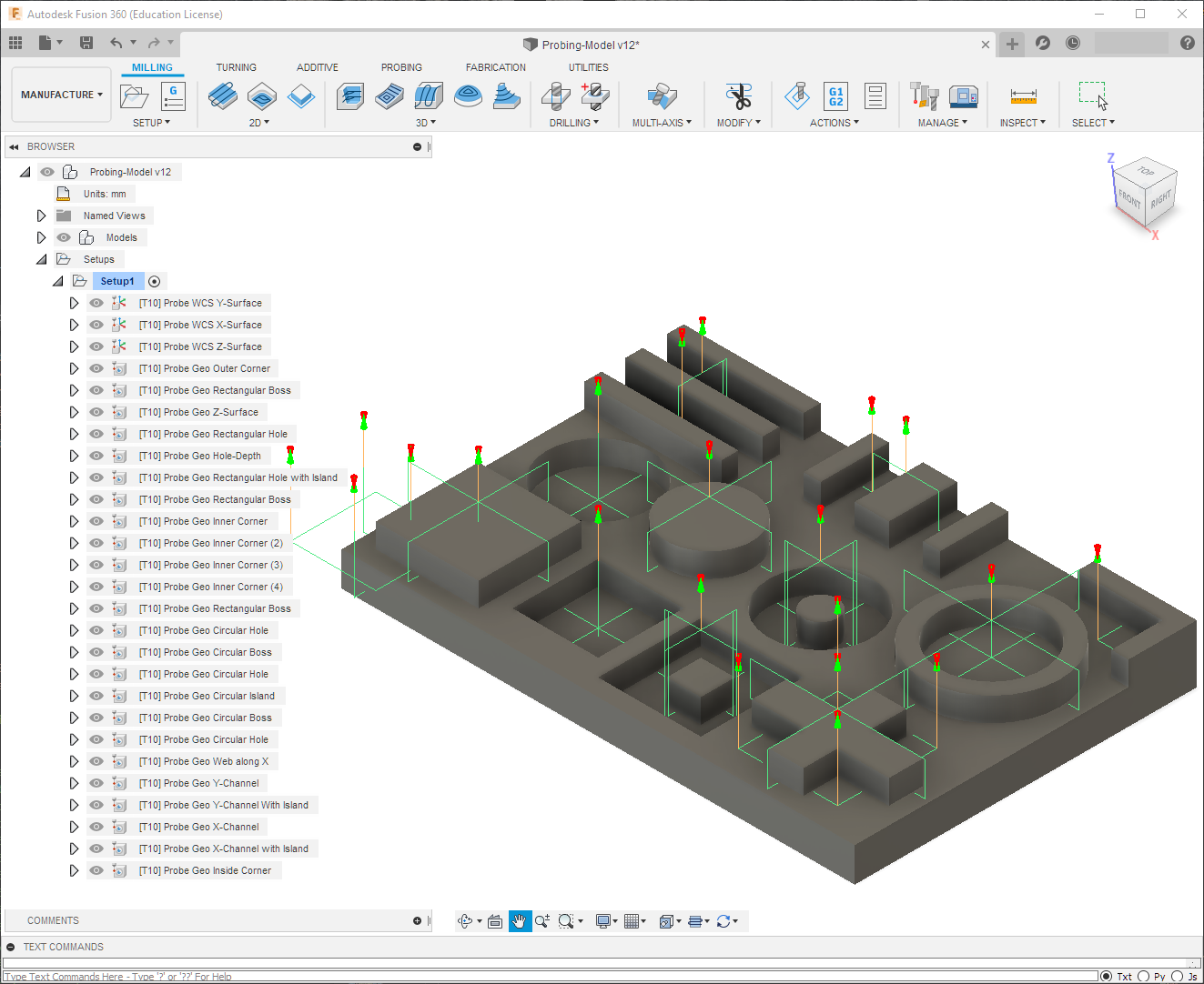
Fusion 360 has the capability to add WCS and Geometry Probing cycles directly into your program together with the Tool Path operations. WCS Probing routines can be used to speed up or even automate robust stock setups while Geometry Probing routines can be used to check features for position and size tolerance and automatically adjust tool diameters and tool offset heights for tool wear.
This guide does not cover how to use the Fusion 360 probing cycles and just goes into details how the different options that are available within the Probing Cycles do effect the Centroid specific implementation of the probing functionality. If you are unfamiliar with the Fusion 360 probing functionality, there’s plenty of information on the Internet. Here are just a few examples:
Implementation Details
One requirement for the Fusion 360 Probing functions to work is that the Post Processor needs to support the Probing Functionality but that’s just the easy part. Looking at the output the post processor generates for the probing routines reveals the more difficult part. Here’s an example of the generated blocks:
(PROBE WCS Y-SURFACE)
N30 T10 M06
N35 G54
N40 G00 A0.
N45 G00 X9.117 Y-5.5
N50 G43 Z15. H10
N55 G65 P9832
N60 G65 P9810 Z5. F1000.
N65 G65 P9810 Z-12.
N70 G65 P9811 Y0. Q2. M1. W1. S1.
N75 G65 P9810 Z5.
N80 G00 Z15.
N85 G65 P9833
As seen in the example above, the probing commands are just subprogram calls in the form of P98xx with a bunch of parameters and these subprogram don’t exist for the Centroid Acorn board. I took on the challange to write probing cycles to fully implement the functionality of the Fusion 360 WCS and Geometry probing cycles supporting all available options. Contact me if you are interested in these probing routines.
Supported Probing Cycles
The following WCS and Geometry Probing Cycles are supported:
- Single Surface XYZ (P9811)
- Wall/Web XY (P9812)
- Channel/Slot XY (P9813)
- Circular Boss XY (P9814)
- Circular Hole XY (P9817)
- Rectangular Boss XY (P9812 C1)
- Rectangular Hole XY (P9813 C1)
- Inner Corner XY (P9815)
- Outer Corner XY (P9816)
- Plane Angle XY (P9843)
Special Probing Functions
In addition to the probing cycle sub-programs above, there are these supporting sub-programs:
Reporting/Print Function
The WCS as well as the Geometry Probing Cycles do have a reporting function to record/print probing results to a log file. The name of the log file can be configured in the parameter configuration file (See Probing Customization for details.)
Here’s an example of the information recorded by the Print Function:
------------------------------------------------------------
Log Date: Mon May  4 13:43:23 2020
------------------------------------------------------------
 COMPONENT NO 1                          FEATURE NO 1
------------------------------------------------------------
WORK OFFSET #1  SURFACE Y
POS Y0.000  ACTUAL 0.003  DEV 0.003  TOL 1.000

    +++++WCS #1 POS Y0.003 UPDATED TO Y0.000+++++

------------------------------------------------------------
 COMPONENT NO 1                          FEATURE NO 2
------------------------------------------------------------
WORK OFFSET #1  SURFACE X
POS X0.000  ACTUAL -0.005  DEV -0.005  TOL 1.000

    +++++WCS #1 POS X-0.005 UPDATED TO X0.000+++++

------------------------------------------------------------
 COMPONENT NO 1                          FEATURE NO 3
------------------------------------------------------------
WORK OFFSET #1  SURFACE Z
POS Z0.000  ACTUAL 0.006  DEV 0.006  TOL 1.000

    +++++WCS #1 POS Z0.006 UPDATED TO Z0.000+++++

------------------------------------------------------------
 COMPONENT NO 1                          FEATURE NO 4
------------------------------------------------------------
GEOMETRY  XY OUTER CORNER
CORNER POS-X 5.000  ACTUAL 4.869  DEV -0.131  TOL 0.500  PASSED
CORNER POS-Y 5.000  ACTUAL 4.841  DEV -0.159  TOL 0.500  PASSED
ANGLE SURFACE-X DEG 0  ACTUAL 0.145  DEV 0.145  TOL 1.000  PASSED
ANGLE SURFACE-Y DEG 0  ACTUAL 0.111  DEV 0.111  TOL 1.000  PASSED
------------------------------------------------------------
 COMPONENT NO 1                          FEATURE NO 5
------------------------------------------------------------
GEOMETRY  XY INNER CORNER
CORNER POS-X 130.000  ACTUAL 129.632  DEV -0.368  TOL 0.500  PASSED
CORNER POS-Y 15.000  ACTUAL 14.458  DEV -0.542  TOL 0.500

    +++++WCS Y POS OUT OF TOLERANCE+++++ERROR -0.042

ANGLE SURFACE-X DEG 0  ACTUAL -0.474  DEV -0.474  TOL 1.000  PASSED
ANGLE SURFACE-Y DEG 0  ACTUAL 0.413  DEV 0.413  TOL 1.000  PASSED
Note that the “Component No” is stored in the non-volatile variable #155 by default (can be changed in the configuration parameters) and will keep the value between CNC12 sessions. Everytime the check box “Increment Component” in the Action Tab of the Fusion 360 Probing Cycle Setup is checked, the Component No will be incremented and the Feature No reset to 1.
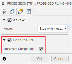
It is recommended to check the box “Increment Component” in the first probing cycle to increment the Component No and start with a fresh count of the Feature No.
Probing Cuctomization
Many aspects of the probing cycles can be customized.
See Probing Customization for all the possible configuration options.