Fusion 360 Milling Post Processor for Centroid
General Milling Post Processor for Centroid with additional Features
Project maintained by swissi2000 Hosted on GitHub Pages — Theme by mattgraham
Fusion 360 Probing Cycle: Outer Corner XY
Description
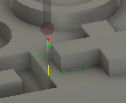
Calculates the exact corner position by measuring two points on each of the two corner surface. Based on the two measurements on each corner surface, the angle of the surface as well as the crossing point of the two vectors can be calculates to determine the exact corner point.
WCS Probing Cycle
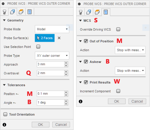
A typical block for a Outer Corner Probing Cycle looks like this:
G65 P9816 X105. Y15. Q2. B1. M0.1 W1. S1
Parameter X: Expected X Position
Sets the expected X position of the corner surface that runs along the Y-Axis. The first probing point will be taken at the current probe position when the P9815 probing cycle is commanded. The 2nd probing point is 2/3 the distance from the first point to the expected corner position.
Parameter Y: Expected Y Position
Sets the expected Y position of the corner surface that runs along the X-Axis. The first probing point will be taken at the current probe position when the P9815 probing cycle is commanded. The 2nd probing point is 2/3 the distance from the first point to the expected corner position.
Parameter Q: Overtravel Distance
The overtravel distance defines how far the probe is allowed to travel passed the expected surface position before the probing move is aborted with a “Surface not found” error.
Parameter B: Askew Tolerance
Sets the askew tolerance in degrees that a surface is allowed to have and works in conjunction with the “Askew” check box in the Action Tab to stop the WCS probing cycle with an “Angle out of Tolerance” message.
Parameter M: Position Tolerance
This parameter defines the position error the corner point is allowed to have and works in conjunction with the “Out of Position” check box in the Action Tab to stop the WCS probing cycle and display an “Out of Tolerance” message.
Parameter W: Print Results
Possible values are W1 and W2 where W1 just increments the “Feature” number while W2 does increment the “Component” number and resets the “Feature” number to 1. See Print Results for more details.
Parameter S: WCS
Defines the WCS # that will be reset by this probing cycle. By default this is the currently active, driving WCS and can be changed in the “Actions” tab with the “Overwrite Driving WCS” check box. Note that the Free version of CNC12 only supports WCS #1 (G54), Mill Pro supports WCS # 1-6 (G54 - G59) and Mill Digitizing Bundle supports WCS #1-18 (G54 - G59 and E7 - E18).
Geometry Probing Cycle
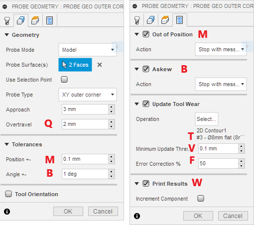
A typical block for a Inner Corner Probing Cycle looks like this:
G65 P9816 X105. Y15. Q2. B1. F0.5 M0.1 T3. V0.1 W1.
Parameter X: Expected X Position
Sets the expected X position of the corner surface that runs along the Y-Axis. The first probing point will be taken at the current probe position when the P9815 probing cycle is commanded. The 2nd probing point is 2/3 the distance from the first point to the expected corner position.
Parameter Y: Expected Y Position
Sets the expected Y position of the corner surface that runs along the X-Axis. The first probing point will be taken at the current probe position when the P9815 probing cycle is commanded. The 2nd probing point is 2/3 the distance from the first point to the expected corner position.
Parameter Q: Overtravel Distance
The overtravel distance defines how far the probe is allowed to travel passed the expected surface position before the probing move is aborted with a “Surface not found” error.
Parameter B: Askew Tolerance
Sets the askew tolerance in degrees that a surface is allowed to have and works in conjunction with the “Askew” check box in the Action Tab to stop the Geometry probing cycle with an “Angle out of Tolerance” message.
Parameter F: Error Correction Factor
This % Factor determines how much of the measured error should be applied to correct tool wear. This parameter is only present if Tool Wear adjustment has been selected.
Parameter M: Position Tolerance
This parameter defines the position error the corner point is allowed to have and works in conjunction with the “Out of Position” check box in the Action Tab to stop the WCS probing cycle and display an “Out of Tolerance” message.
Parameter T: Tool Offset Number
This number defines the Tool Diameter Offset that will be adjusted for wear. Note that the Fusion 360 as well as the CNC12 Tool Library allow to configure tool diameter offsets that don’t match the actual tool number. That means in theory tool number 3 could have a diameter offset number 10. This parameter is only present if Tool Wear adjustment has been selected.
Parameter V: Minimum Update Threshold
Defines the threshold value that will trigger a wear adjustment. If the measured error is below the threshold value, no wear adjustment will be made. This parameter is only present if Tool Wear adjustment has been selected.
Parameter W: Print Results
Possible values are W1 and W2 where W1 just increments the “Feature” number while W2 does increment the “Component” number and resets the “Feature” number to 1. See Print Results for more details.
[Use Browser Back Button to Return]