Fusion 360 Milling Post Processor for Centroid
General Milling Post Processor for Centroid with additional Features
Project maintained by swissi2000 Hosted on GitHub Pages — Theme by mattgraham
Fusion 360 Probing Cycle: Rectangular Boss XY
Description
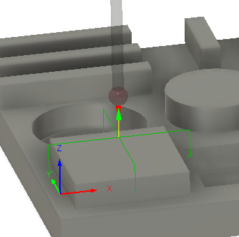
Measures the exact position of all 4 walls of a rectangular boss and positions the probe at the center of the boss at the end of the probing cycle. The probing cycle is the same as the Wall/Web probing cycle. The parameter C1 indicates to the probing cycle to probe a boss in the X and Y direction and not just a Wall/Web.
The probing cycle consists of two probing commands, one to measure in the X direction and one for the Y direction. No messages will be displayed or printed until both probing commands have been completed.
WCS Probing Cycle
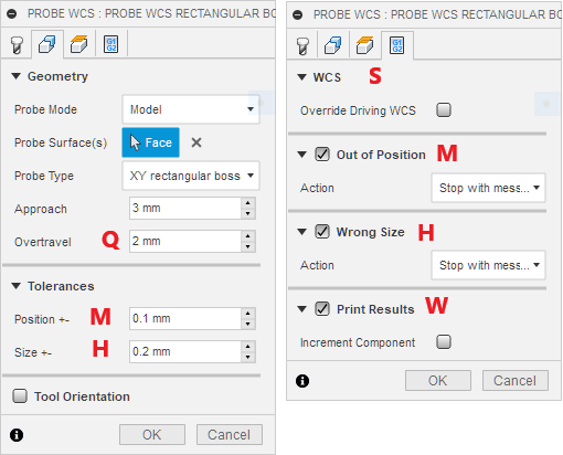
The two blocks for a Rectangular Boss Probing Cycle look like this:
G65 P9812 A1 C1 Z-2.5 X30. R1. Q2. H0.2 M0.1 W1. S1
G65 P9812 A2 C1 Z-2.5 Y30. R1. Q2. H0.2 M0.1 W1. S1
Parameter A: Axis Index
Parameter A is the Axis Index where Axis X=1, Y=2. The first probing move will be in the X direction, the second probing move in the Y direction.
Parameter C: Rectangular Boss Indicator
Parameter C1 indicates to the probing cycle that a rectangular boss needs to be measured and not just a single Wall/Web. Both Wall/Web probing cycles in the X and Y direction will be completed before displaying/printing results and setting WCS.
Parameter Z: Probing Height
Sets the Z-Position for the probe to drop down to to measure the Rectangular Boss surfaces.
Parameter X or Y: Expected Boss Width
The value of parameter X or Y holds the expected Boss Width for each direction based on the Fusion 360 model. The probing cycle will start at the expected center of the Boss. This parameter must match the Axis Index A, that means if Axis Index is A1, then a X value is expected, for A2 it must be Y.
Parameter R: Approach Distance
Sets the distance the probe will travel passed the expected Wall position before dropping down on Z to the probing height or with other words, this is the distance the probe will travel from the start of the probing move to the expected Wall position.
Parameter Q: Overtravel Distance
The overtravel distance defines how far the probe is allowed to travel passed the expected surface position before the probing move is aborted with a “Surface not found” error.
Parameter H: Size Tolerance
This parameter defines the size error the boss width is allowed to have and works in conjunction with the “Wrong Size” check box in the Action Tab to stop the WCS probing cycle and display an “Wrong Size” message.
Parameter M: Position Tolerance
This parameter defines the position error the center of the boss is allowed to have and works in conjunction with the “Out of Position” check box in the Action Tab to stop the WCS probing cycle and display an “Out of Tolerance” message.
Parameter W: Print Results
Possible values are W1 and W2 where W1 just increments the “Feature” number while W2 does increment the “Component” number and resets the “Feature” number to 1. See Print Results for more details.
Parameter S: WCS
Defines the WCS # that will be reset by this probing cycle. By default this is the currently active, driving WCS and can be changed in the “Actions” tab with the “Overwrite Driving WCS” check box. Note that the Free version of CNC12 only supports WCS #1 (G54), Mill Pro supports WCS # 1-6 (G54 - G59) and Mill Digitizing Bundle supports WCS #1-18 (G54 - G59 and E7 - E18).
Geometry Probing Cycle
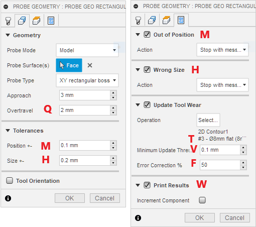
The two blocks for a Rectangular Boss Probing Cycle look like this:
G65 P9812 A1 C1 Z-2.5 X30. R1. Q2. F0.5 H0.2 M0.1 T3. V0.1 W1.
G65 P9812 A2 C1 Z-2.5 Y30. R1. Q2. F0.5 H0.2 M0.1 T3. V0.1 W1.
Parameter A: Axis Index
Parameter A is the Axis Index where Axis X=1, Y=2. The first probing move will be in the X direction, the second probing move in the Y direction.
Parameter C: Boss Indicator
Parameter C1 indicates to the probing cycle that a boss needs to be measured and not just a single Wall/Web. Both Wall/Web probing cycles in the X and Y direction will be completed before displaying/printing results.
Parameter X or Y: Expected Boss Width
The value of parameter X or Y holds the expected Wall/Web Width to be probed based on the Fusion 360 model. The probing cycle will start at the expected center of the Boss. This parameter must match the Axis Index A, that means if Axis Index is A1, then a X value is expected, for A2 it must be Y.
Parameter Z: Probing Height
Sets the Z-Position for the probe to drop down to to measure the Rectangular Boss surfaces.
Parameter R: Approach Distance
Sets the distance the probe will travel passed the expected Wall position before dropping down on Z to the probing height or with other words, this is the distance the probe will travel from the start of the probing move to the expected Wall position.
Parameter Q: Overtravel Distance
The overtravel distance defines how far the probe is allowed to travel passed the expected surface position before the probing move is aborted with a “Surface not found” error.
Parameter F: Error Correction Factor
This % Factor determines how much of the measured error should be applied to correct tool wear. This parameter is only present if Tool Wear adjustment has been selected.
Parameter H: Size Tolerance
This parameter defines the size error the boss width is allowed to have and works in conjunction with the “Wrong Size” check box in the Action Tab to stop the Geometry probing cycle and display a “Wrong Size” message.
Parameter M: Position Tolerance
This parameter defines the position error the center of the boss is allowed to have and works in conjunction with the “Out of Position” check box in the Action Tab to stop the Geometry probing cycle and display an “Out of Tolerance” message.
Parameter T: Tool Offset Number
This number defines the Tool Diameter Offset that will be adjusted for wear. Note that the Fusion 360 as well as the CNC12 Tool Library allow to configure tool diameter offsets that don’t match the actual tool number. That means in theory tool number 3 could have a diameter offset number 10. This parameter is only present if Tool Wear adjustment has been selected.
Parameter V: Minimum Update Threshold
Defines the threshold value that will trigger a wear adjustment. If the measured error is below the threshold value, no wear adjustment will be made. This parameter is only present if Tool Wear adjustment has been selected.
Parameter W: Print Results
Possible values are W1 and W2 where W1 just increments the “Feature” number while W2 does increment the “Component” number and resets the “Feature” number to 1. See Print Results for more details.
[Use Browser Back Button to Return]