Fusion 360 Milling Post Processor for Centroid
General Milling Post Processor for Centroid with additional Features
Project maintained by swissi2000 Hosted on GitHub Pages — Theme by mattgraham
Fusion 360 Probing Customization Parameters
Description
Many features of the Fusion 360 Probing Cycles for Centroid can be customized.
All the parameters that can be customized are located in the script file
C:\cncm\probing\probe_initialize.cnc
All the configuration parameters related to Fusion 360 Probing Cycles are in a dedicated, marked section.
Fusion 360 Probing Configuration Parameters
This is the customization section of the configuration file “C:\cncm\probing\probe_initiliza.cnc”:
;--------------------------------------------------------------------------------------------
; Fusion 360 Probing Cycle Parameters
;--------------------------------------------------------------------------------------------
#381   = "c:\cncm\ncfiles\probing-report.log" ; log file to record Fusion 360 probing results
#33998 = 0   ; 0=Fast Probing Move first then slow, 1=skip fast probing move and do only slow
#33997 = 0   ; Display WCS measurements before setting WCS. -1=No display, 0=message needs to be confirmed with Cycle Start, >0=Wait time in seconds
#33996 = 0   ; Display Geometry measurements. -1=No display, 0=message needs to be confirmed with Cycle Start, >0=Wait time in seconds
#33995 = 0   ; Display Tool Wear adjustment message. -1=No display, 0=message needs to be confirmed with Cycle Start, >0=Wait time in seconds
;#33994      ; Reserved for Feature # used for Printing Function
#33993 = 155 ; non volatile user parameter that keeps component # for probing log (possible 150 - 159)
#33992 = 0   ; Out of Tolerance Messages: -1 = do not show, 0 = wait for confirmation, >0 = display time in seconds
#33991 = 0   ; Display CSR Active Warning Message, 0 = Display, 1 = Do not display
#33990 = 0.5 ; Max. Tool Wear adjustment allowed (always in mm). 0=No Limit. No adjustment will be made if this amount is exceeded and a warning message will be presented
Print File Name (#381)
The user text variable #381 specifies the file name used to print/log probing results if this function was selected in the Fusion 360 probing cycle. Any valid file name can be used. The default file name is:
#381 = "c:\cncm\ncfiles\probing-report.log"
Fast/Slow Probing Sequence (#33998)
This parameter allows to configure the preferred probing sequence.
Options are:
0 = (Default) Fast probing move first followed by a slow probing move
1 = Slow probing move only
Display WCS Measurements (#33997)
This parameter allows to customize the way WCS Measurements are displayed before WCS is set.
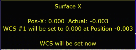
Options are:
-1 = No display. WCS will be set without showing WCS Measurements
 0 = (Default) WCS Measurements are displayed and need to be confirmed with *Cycle Start*
>0 = A value larger than 0 will set the number of seconds the WCS Measurements will be displayed before automatic continuation
Display Geometry Measurements (#33996)
This parameter allows to customize the way Geometry Measurements are displayed.
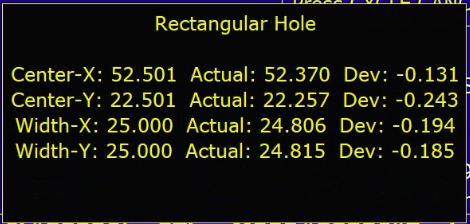
Options are:
-1 = No Measurements are displayed
 0 = (Default) Geometry Measurements are displayed and need to be confirmed with *Cycle Start*
>0 = A value larger than 0 will set the number of seconds the Geometry Measurements will be displayed before automatic continuation
Display Tool Wear Adjustment Message (#33995)
This parameter allows to customize the way Tool Wear Messages are displayed before Tool Dameter or Height Offsets are adjusted.

Options are:
-1 = No display. Tool Offsets will be adjusted without showing a message first
 0 = (Default) Tool Wear adjustment values are displayed and need to be confirmed with *Cycle Start*
>0 = A value larger than 0 will set the number of seconds the Tool Wear adjustment message will be displayed before automatic continuation
Component No Variable (#33993)
By default the Component No is stored in the non-volatile variable #155. If this variable is already used for another function, a different variable can be assigned.
Options are:
150 - 159
Out of Tolerance Message (#33992)
This parameter allows to customize the way the Out of Tolerance Messages are displayed.
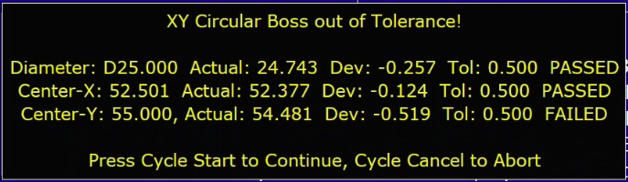
Options are:
-1 = No display on screen. Results will be printed to log file if Print Option was selected
 0 = (Default) Out of Tolerance Messages are displayed and need to be confirmed with *Cycle Start*
>0 = A value larger than 0 will set the number of seconds the Out of Tolerance message will be displayed before automatic continuation
CSR Active Warning Message (#33991)
This parameter allows to customize the way the CRS Active Warning Messages are displayed. CNC12 allows to rotate the coordinate system (CSR) but the CNC12 probing moves do ignore CSR. All the probing moves are always going straight along the physical. As probing cycles with activated CSR can result in unexpected results, a warning message is being displayed in such situations.
Options are:
0 = (Default) CSR Warning Messages are displayed
1 = No CSR Warning messages will be displayed
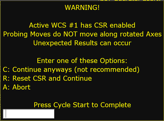
When a CSR Warning is displayed, the user can choose from the following options:
C = Continue with CSR enabled
R = Reset CSR and continue
A = Abort Probing Cycle
Max. Tool Wear adjustment (#33990)
This parameter sets the maximum allowed Tool Wear adjustment value (Tool Diameter Offset for X and Y measurements and Tool Height Offset for Z measurements). If this parameter is 0, there will be no set maximum and all Tool Wear Offsets will be applied. The value of this parameter MUST be in millimeters (mm)! It will be converted automatically for probing cycles in Imperial.
No Tool Wear adjustments will be made if the calculated adjustment value exceeds the maximum allowed value.
Options are:
 0 = No maximum
>0 = (Default = 0.5mm) Maximum allowed Tool Offset adjustment value MUST be in millimeter (mm) and will be converted if needed
[Use Browser Back Button to Return]