Fusion 360 Milling Post Processor for Centroid
General Milling Post Processor for Centroid with additional Features
Project maintained by swissi2000 Hosted on GitHub Pages — Theme by mattgraham
Fusion 360 Probing Cycle: Plane Angle XY
Description
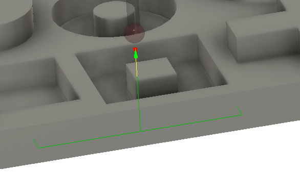
Measures two points on a plane and calculates the plane angle. While the WCS Plane Angle probing cycle can be used to automatically set Cordinate System Rotation (CSR), it is important to know that the CNC12 probing commands do ignore CSR angles. All probing moves always go straight along the physical X and Y axes so executing probing moves while CSR is activated can lead to unexpected results.
WCS Probing Cycle
A typical block for a Plane Angle Probing Cycle looks like this:
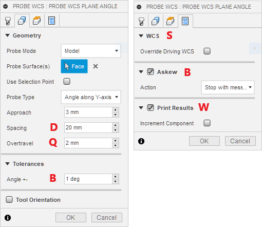
G65 P9843 A2 Y0. D50. Q2. B1. W1. S1
Parameter A: Axis Index
Parameter A is the Axis Index where Axis X=1, Y=2, so A2 in the example above indicates a probing move along the Y-Axis to measure the angle of a surface that runs along the X-Axis.
Parameter X or Y: Expected Surface Position
The value of parameter X or Y holds the expected position of the surface to be measured based on the Fusion 360 model. The probing cycle will start at the current probe position. This parameter must match the Axis Index A, that means if Axis Index is A1, then a X value is expected, for A2 it must be Y.
Parameter D: Distance between Probing Points
Sets the distance between the two probing points. The probing cycle will start at the current probe position and will move D/2 to the axis negative direction for the first probing point and then distance D to the plus direction for the 2nd probing point.
Parameter Q: Overtravel Distance
The overtravel distance defines how far the probe is allowed to travel passed the expected surface position before the probing move is aborted with a “Surface not found” error.
Parameter B: Askew Tolerance
Sets the askew tolerance in degrees that a surface is allowed to have and works in conjunction with the “Askew” check box in the Action Tab to stop the WCS probing cycle with an “Angle out of Tolerance” message.
Parameter W: Print Results
Possible values are W1 and W2 where W1 just increments the “Feature” number while W2 does increment the “Component” number and resets the “Feature” number to 1. See Print Results for more details.
Parameter S: WCS
Defines the WCS # that will be reset by this probing cycle. By default this is the currently active, driving WCS and can be changed in the “Actions” tab with the “Overwrite Driving WCS” check box. Note that the Free version of CNC12 only supports WCS #1 (G54), Mill Pro supports WCS # 1-6 (G54 - G59) and Mill Digitizing Bundle supports WCS #1-18 (G54 - G59 and E7 - E18).
Geometry Probing Cycle
A typical block for a Plane Angle Probing Cycle looks like this:
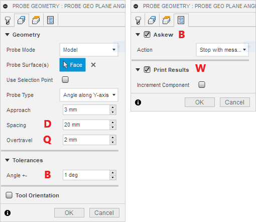
G65 P9843 A2 Y0. D50. Q2. B1. W1.
Parameter A: Axis Index
Parameter A is the Axis Index where Axis X=1, Y=2, so A2 in the example above indicates a probing move along the Y-Axis to measure the angle of a surface that runs along the X-Axis.
Parameter X or Y: Expected Surface Position
The value of parameter X or Y holds the expected position of the surface to be measured based on the Fusion 360 model. The probing cycle will start at the current probe position. This parameter must match the Axis Index A, that means if Axis Index is A1, then a X value is expected, for A2 it must be Y.
Parameter D: Distance between Probing Points
Sets the distance between the two probing points. The probing cycle will start at the current probe position and will move D/2 to the axis negative direction for the first probing point and then distance D to the plus direction for the 2nd probing point.
Parameter Q: Overtravel Distance
The overtravel distance defines how far the probe is allowed to travel passed the expected surface position before the probing move is aborted with a “Surface not found” error.
Parameter B: Askew Tolerance
Sets the askew tolerance in degrees that a surface is allowed to have and works in conjunction with the “Askew” check box in the Action Tab to stop the WCS probing cycle with an “Angle out of Tolerance” message.
Parameter W: Print Results
Possible values are W1 and W2 where W1 just increments the “Feature” number while W2 does increment the “Component” number and resets the “Feature” number to 1. See Print Results for more details.
[Use Browser Back Button to Return]