ProbeApp for Centroid CNC12
ProbeApp for Mill & Routers that integrates with Centroid CNC12
Project maintained by swissi2000 Hosted on GitHub Pages — Theme by mattgraham
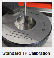
Standard Touch Probe Calibration
The Standard Touch Probe Calibration function is located in the Configuration and Utilities section.
Gear Icon on the ProbeApp Main Screen 
Why calibrate a Touch Probe
Most mechanical Touch Probes used in the DIY space are based on a design like this:
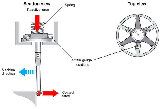
Touch Probes based on this design usually have no pre-travel when triggered along the stylus axis for Z-axis measurements. The same is not true when the touch probe stylus is triggered in the X-Y-Plane. There is a pre-travel of the stylus before a trigger signal occurs and because of the 3 leg design, that pre-travel is not uniform over a 360 degree trigger range.
There’s not just a pre-travel variation caused by the geometry of the trigger mechanism, there’s also a significant variation in stylus deflection caused by the change in trip-force based on the trip angle. The difference in required trip-force can easily exceed 50g based on the trip angle.
If you wonder how much deflection a trip force of 50g can cause to your stylus, enter the parameters of your probes stylus into this Deflection Calculator and be surprised.
If you want to get a better picture about the trigger characteristic of you Touch Probe, I recommend to create a Trip Map as descibed in this Chapter.
The Trip Map will help to find the best position in the Touch Probe Trigger Pattern that has the least pre-travel variance in the X+/X- and Y+//Y- direction. It will also give you a pretty good picture of what overall accuracy you can expect from your touch probe.
If the pre-travel distance in the four main directions X+/X- and Y+/Y- varies significantly, you can consider the Precision Calibration Method as described in this Chapter as this method will compensate for the pre-travel distance in the four main directions individually.
Calibration Process
The best way to calibrate a Touch Probe is to use a Ring Gauge that has a very precise known diameter.
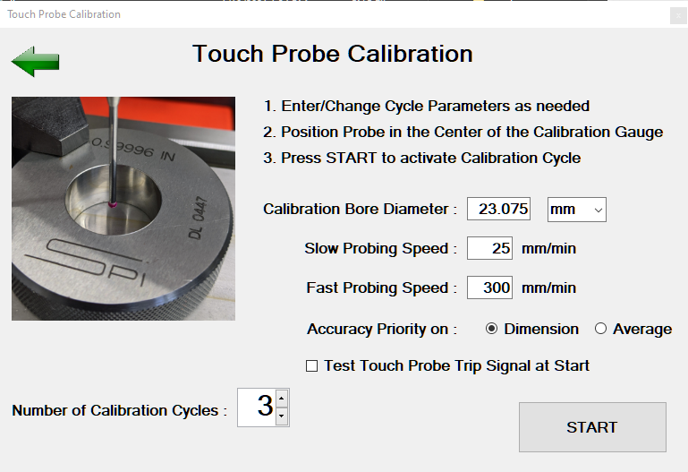
This calibration cycle has the following Input fields:
Calibration Bore Diameter
This is the diameter that’s usually engraved on the Ring Gauge. The units of the Ring Gauge can be selected. This will allow to use a mm Gauge on an Imperial machine (or vice versa) without having to convert the diameter manually to match the machines units.
Probing Speed
The default fast an slow probing feed rates are pre-populated. Only change these feed rates if you want to experiment if you can get more precise results by reducing the feed rate of if you can increase the feed rate without impacting the accuracy.
Note that changing the feed rates here does not change your default probing feed rates configured in CNC12. If you experimented here with feed rates and want to change them permanently, you have to make those changes manually in the CNC12 parameter section (Parameter 15 = Slow Probing Feed Rate, 14 = Fast Probing Feed Rate)
Accuracy Priority
The Options here are Dimension or Average
With a default Bore measuring cycle, the Touch Probe tip is being placed inside the bore at the approximate center. The first probing move is always along the X-axis. This measurement will be used to find the exact bore center along the X-axis but cannot be used to determine the actual bore diameter as we are most likely a little bit off-center in the Y-axis direction after having placed the touch probe tip manually in the approximate center.
After having found the center of the bore along the X-axis, the second probing cycle willl be along the Y-axis and this cycle will determine the bore center as well as the bore diameter.
That means that it will always be the measurement along the Y-axis that determines the diameter of a bore but as I have described above, there’s most likely a pre-travel variance along the X-axis compared to the Y-axis.
The selection on Priority on Dimension or Average will give you the option how to handle possible measurement errors between the measurement along the X and the Y axis:
Priority on Dimension
With this option, only measurements along the Y-axis are being used to average the pre-travel distance to calculate the pre-travel compensated probe tip diameter.
This option will give you the most accurate bore measurements and all other touch probe measurements along the Y-axis but there could be potentially a larger error for measurements along the X-axis.
Priority on Average
With this option, the calibration cycle will use all measurements in the X and Y axis to average out the pre-travel in all four directions to calculate the pre-travel compensated probe tip diameter.
This option might give you a less accurate measurement in bore diameter but will give you better measurement averages over all four probing directions.
Test Touch Probe Trip Signal at Start
If this box is checked, the calibration cycle will start with a loop looking for a touch probe trip signal. Trip the touch probe manually and the loop will end with a confirmation message that the trip signal was recognized.
Number of Calibration Cycles
Select how many calibration cycles you want to run. The options are between 2 and 10 cycles.
START
After all data has been entered, place the touch probe tip in the approximate center of the Gauge Bore and press the START button.
The presented messages during the calibration cycle will be a little different for the Priority on Dimension and Priority on Average option:
Priority on Dimension
With this option, only diameter measurements along the Y-axis are being averaged. A message will tell you what the maximum deviation was between the diameter measurements of all the selected cycles and will also display the pre-travel adjusted, calibrated probe tip diameter.
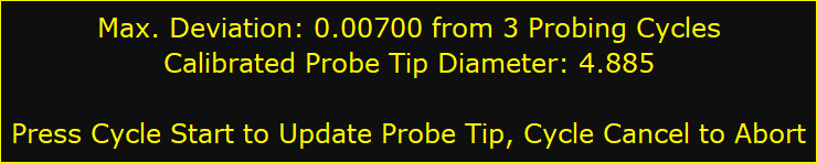
If you press Cycle Start, the probe tip diameter in CNC12 will be updated with the new, calibrated diameter value. A Cycle Cancel will abort the calibration cycle and CNC12 will not be updated.
After confirming the new probe tip diameter update with Cycle Start this message will be displayed:
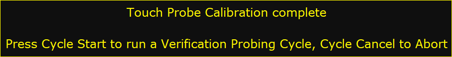
Pressing Cycle Start again will initiate a Bore measurement cycle with the new, adjusted probe tip diameter and will display the result of the measurement:
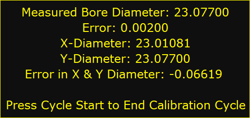
In this example, the measured bore diameter is within 2 micrometers but the measured error between the X and Y axis diameter is over 66 micrometer.
Priority on Average
With this option, all diameter measurements along the X and Y-axis are being averaged. A message will tell you what the maximum deviation was between the diameter measurements of all the selected cycles and will also display the pre-travel adjusted, calibrated probe tip diameter.
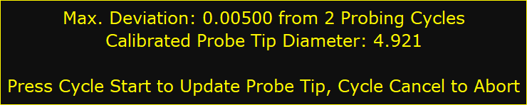
If you press Cycle Start, the probe tip diameter in CNC12 will be updated with the new, calibrated diameter value. A Cycle Cancel will abort the calibration cycle and CNC12 will not be updated.
After confirming the new probe tip diameter update with Cycle Start this message will be displayed:
Pressing Cycle Start again will initiate a Bore measurement cycle with the new, adjusted probe tip diameter and will display the result of the measurement:
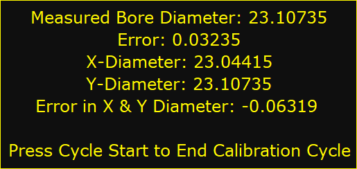
Compared to the Priority on Dimension method above, the error between the X and Y axis measurement is still the same with 63 micrometers as expected, but the overall measuring error is now more averaged between the X and Y axis measurement.
Consideration
If the difference between X and Y axis measurements is significant, you can consider the Precision Calibration Method as described in this Chapter.
This method will compensate for the pre-travel distance in the four main directions individually and might give you overall more accurate results.