ProbeApp for Centroid CNC12
ProbeApp for Mill & Routers that integrates with Centroid CNC12
Project maintained by swissi2000 Hosted on GitHub Pages — Theme by mattgraham
Touch Probe Trip Map
The Touch Probe Trip Map function is located in the Configuration and Utilities section.
Gear Icon on the ProbeApp Main Screen 
There are several factors that impact overall probing accuracy.
The most important factors related directly to the Touch Probe are:
-
Repeatability. This is the variance of measuring the same feature multiple times. The repeatability of a mechanical Touch Probe is usually within a couple of micrometers (1 micrometer = 0.001mm ~ 0.00004”)
-
Trip Force Variation. Caused by the typical 3-leg trip mechanism of a mechanical Touch Probe, the required force at the probe tip to create a trip signal can vary significantly based on the angle the stylus is tripped. On a typical mechanical Touch Probe, this trip force can vary between 50g and over 100g of force. That means that the trip force variance can easily exceed 50g of force. See Stylus Deflection for an explanation what such a variation in trip force can cause.
-
Stylus Deflection. This is the distance a probe stylus does bend from the point when the trip force is applied to the stylus tip to the point when the whole trip force that’s necessary to trip the TP is applied. The legth, diameter and material of the stylus as well as the required trip force are the important factors here and deflection can be very significant. As mentioned in Trip Force Variation, the force variation can easily exceed 50g of force. To get a good picture what kind of deflection a trip force variation of 50g can cause, enter the values of your stylus into this Deflection Calculator.
-
Pre-Travel Variation. Pre-travel is the distance from the point when the probe stylus touches the surface to the point when the control recognized the trip signal. Like the trip force variation, the geometry of the trip mechanism causes a variation of the pre-travel distance based on the trip angle. Some but not all of this pre-travel variation comes from the stylus deflection based on the trip force variation. It’s also important to understand that probing feedrates need to be taken into considerations here. The CNC control does have a certain latency to recognize a trip signal. That means the higher the probing feedrate, the farther the machine will travel before it will react. It’s therefore essential that the slow probing feedrate is set at a low level.
-
Stylus run-out. This is the concentricity error between the center of the spindle and the center of the probe stylus tip. Most Touch Probes have adjustment screws to align the center of the probe tip with the center of the spindle. It’s needless to say that this should be aligned as accurately as possible.
Of course overall probing accuracy does not only depend on the accuracy of the Touch Probe but also on the accuracy of the machine. These are the most important factors:
-
Lead Screw Turn Ratio. Of course the overall probing accuracy can only be as good as the precision of the lead screw. An accurate calibration of the lead screw is essential.
-
Back Lash. In order to get the best probing accuracy, Back Lash Compensation should be activated and properly calibrated.
-
Spindle Tram. It’s very important that not just the spindle axis is perpendicular to the machine bed, but also the Z-axis column on which the spindle moves up and down.
How is the Touch Probe Trip Map been generated
With most Touch Probes, the only data you can get about the accuracy is the Repeatability which usually is very good but as described above, it’s only a small part of the overall probing accuracy you can expect in actual measurements on the machine.
The probing cycle that creates the Touch Probe Trip Map will go around the 360 degrees of a ring gauge and will make a measurement move at every selected degree step. It will record exactly at which point the control has recognized the trip signal. The machine will then reverse and record the point at which the control received the un-trip signal.
These recorded trip and untrip points will then be analyzed and visualized on a Standard Map and a Detailed Map and will give you a brutally honest, real life overview of the measurments, taking into account all the possible issues and the error sum of their accumulation as mentioned above.
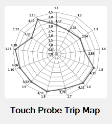
Here’s an example of a Standards Map of a Centroid KP-3 Touch Probe:
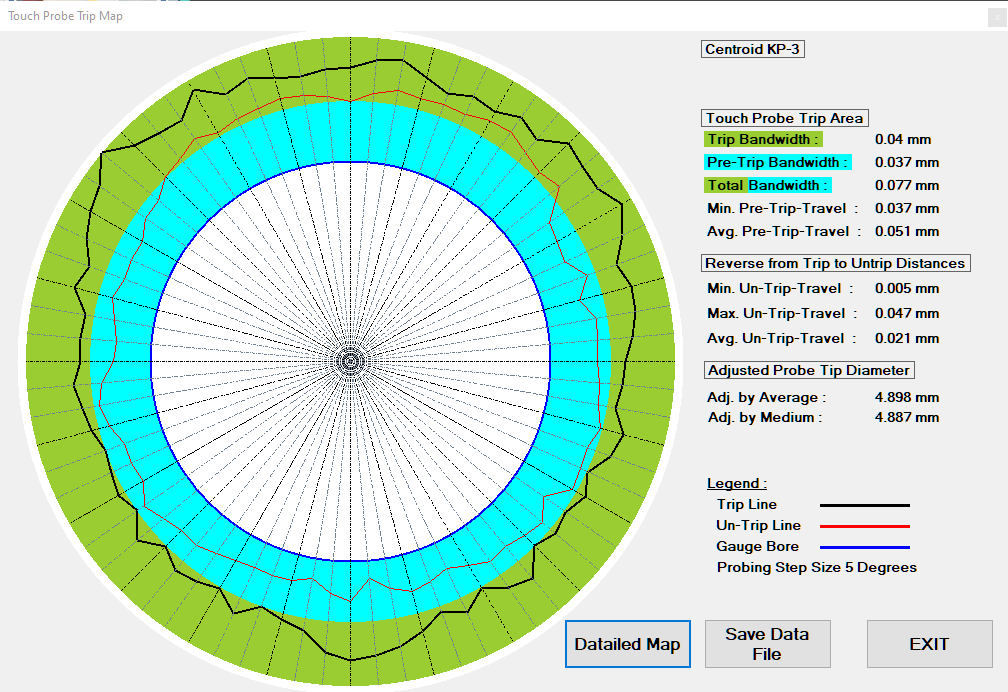
See Chapter Standard Map Description below about the details of this map.
The Detailed Map shows the Trip-Bandwidth in finer resolution:
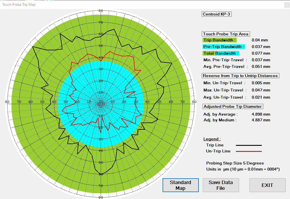
See Chapter Detailed Map Description below about the details of this map.
How to create a Touch Probe Trip Map
See the sections below for a description of the input fields for the Trip Map Cycle:
Touch Probe Name
Free Text-Field that will be printed on top of the Trip Map.
Notes
Free Text-Field that will be printed as comment on top of the Trip Map right underneath the Touch Probe Name text.
Gauge Bore Diameter
This is the diameter that’s usually engraved on the Ring Gauge. The units of the Ring Gauge can be selected. This will allow to use a mm Gauge on an Imperial machine (or vice versa) without having to convert the diameter manually to match the machines units.
Physical Probe Tip Diameter
This is the actual (not the calibration adjusted) diameter of the probe’s stylus tip.
Trip Map Resolution
This defines the step-size in degrees at which measurements will be taken around the 360 degree ring gauge. The lowest value is 1 degree and the highest is 45 degree. The finer the step-size, the finer the Trip Map will be.
Note: The step-size must be a value between 1 - 45 that fits evenly within 360 degrees. As an example, the step-size can be 22.5 degrees or 11.25 degrees but 25 degrees would be rejected.
Set Bore Center with
In order to create an accurate Trip Map, the Touch Probe must be placed at the exact center of the gauge bore. There are two options to choose:
- Set Center with Touch Probe
- Set Center with Center Indicator
Using the Touch Probe itself to find the bore center is a quick way to create a first Trip Map but it is recommended to use a Center Finder for more accurate results as the Touch Probe might not find the exact bore center.
Using a Center Finder will also visualize any tramming issues you might have on your machine. A Center Finder usually extends much further from the spindle than the Touch Probe. That means the spindle Z-axis position is further up the Z-column when the bore center is indicated. When the Center Finder is then replaced with the Touch Probe, the spindle needs to be lowered to get the Touch Probe to probing height. If the Z-axis doesn’t move exactly perpendicular to the machine table, the touch probe will move out of center when the spindle is lowered and that will show up on the Trip Map like this:

Test Touch Probe Trip Signal at Start
If this box is checked, the calibration cycle will start with a loop looking for a touch probe trip signal. Trip the touch probe manually and the loop will end with a confirmation message that the trip signal was recognized.
Show Last Trip Map Button
Pressing this button will open the last created Trip Map. If no Trip Map has been done before, a message will say so.
Show Saved TripMap Button
Pressing this button will show a list of all the Trip Maps that have been saved before and allows to open and display a specific Trip Map.
START
After all data has been entered, press the START button to initiated the Trip Map cycle.
The messages that the Trip Map Cycle displays differ based on the selected option on how to place the Touch Probe at the ring gauge center:
Option Touch Probe
A message will be displayed to place the Touch Probe in the approximate center of the gauge bore

After pressing Cycle Start, a standard Bore Cycle will run first to set the Touch Probe at the center of the gauge bore and then start the Trip Map measuring cycles in the selected step size, starting at the 9 o’clock position going clockwise.
Option Center Indicator
A message will be displayed to use a Center Finder to place the center of the spindle at the exact center of the gauge bore. After the center has been indicated, replace the Center Finder with the Touch Probe and lower the probe tip into the gauge bore at probing height. Make sure you don’t move the X and Y axis after the center has been indicated with the Center Finder before you start the Trip Map cycle.
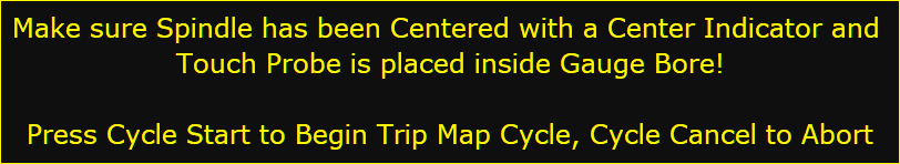
After pressing Cycle Start, the Trip Map measuring cycles will begin in the selected step size, starting at the 9 o’clock position going clockwise.
After all measuring cycles have been recorded, the Standard Trip Map will be displayed. See below for a description of the Trip Maps:
Standard Map Description
-
Center white area. This represents the gauge bore. Note that the dimension of the bore is not proportional in size compared to the blue pre-trip-travel and the green trip bandwidth.
-
Blue Pre-Trip-Travel Bandwidth. This marks the shortest distance the touch probe tip will overtravel the bore before a trip signal is recognized by the control. In this example, the minimum pre-trip-travel distance is 0.037mm.
-
Green Trip-Bandwidth. This area marks the bandwidth from the shortest to the longest distance from the bore center before a trip signal was recorded. In this example, the variance between the shortest and longest measurement is 0.04mm. This variance cannot be compensated for with a probe calibration process. If you now just take the medium of the trip-bandwidth, the average probing accuracy cannot be better than 0.02mm. This can be slightly improved by using the average of all the pre-trip-travel measurements rather than just the medium of the error.
-
Black Trip-Line. This is the line that connects all recorded trip points with each other.
-
Red Un-Trip Line. After a trip point has been recorded, the machine will reverse direction until the touch probe creates an un-trip signal. It’s interesting to see that the areas that have the longest trip point distances also show the longest distance between the trip and the un-trip line. These are the areas that require the largest trip-force and therefore cause more stylus deflection.
-
Measurement Data. On the right side of the Trip Map are the minimum, maximum, medium and average values for the pre-trip-travel and trip-bandwidth. The section Adjusted Probe Tip Diameter shows the best calibrated probe tip diameter values to use based on medium and averaged pre-trip-travel.
-
Detailed Map Button. Press this button to get a more detailed representation of the measured trip points.
-
Save Data File. Press this button to save this Trip Map for later review with a chosen file name. When a new Trip Map cycle is run, ProbeApp will automatically save the old data file in the C:\cncm\probing folder with a name like CNC12_TP_Trip_Map_Data_Year-Month-Day_Hour-Minute-Second.csv.
Detailed Map Description
-
Center Point. Unlike the Standard Trip Map, the center of the map represents the point where the probe tip has reached the surface of the gauge bore. This will show the actual trip points on a finer scale.
-
Blue Pre-Trip-Travel Bandwidth. This marks the shortest distance the touch probe tip will overtravel the bore before a trip signal is recognized by the control. In this example, the minimum pre-travel distance is 37 micrometers which can also be seen on the printed scale.
-
Green Trip-Bandwidth. This area marks the bandwidth from the shortest to the longest distance from the bore center before a trip signal was recorded. In this example, the variance between the shortest and longest measurement is 40 micrometers. This variance cannot be compensated for with a probe calibration process. If you now just take the medium of the trip-bandwidth, the average probing accuracy cannot be better than 0.02mm. This can be slightly improved by using the average of all the pre-trip-travel measurements rather than just the medium of the error. Interesting on this map is to see how the 3-leg trip machanism does impact the trip pattern as the pre-trip-travel tends to be much longer in the leg-areas. Use this map to find the best position of your Touch Probe where the pre-trip-travel variance in the X+/X- and Y+/Y- direction is the most uniform. If you can’t find a position that has an acceptable uniformity in all 4 directions, you might be able to improve probing accuracy by using the Precision Probing Method that uses individual pre-trip-travel corrections in the X+/X- and Y+/Y- directions. See Chapter Precision Touch Probe Calibration for more details.
-
Black Trip Line. This is the line that connects all recorded trip points with each other
-
Red Un-Trip Line. After a trip point has been recorded, the machine will reverse direction until the touch probe creates an un-trip signal. It’s interesting to see that the areas that have the longest trip point distances also show the longest distance between the trip and the un-trip line. These are the areas that require the largest trip-force and therefore cause more stylus deflection.
-
Measurement Data. On the right side of the Trip Map are the minimum, maximum, medium and average values for the pre-trip-travel and trip-bandwidth. The section Adjusted Probe Tip Diameter shows the best calibrated probe tip diameter values to use based on medium and averaged pre-trip-travel.
-
Standard Map Button. Press this button to get back to the standard representation of the measured trip points.
-
Save Data File. Press this button to save this Trip Map for later review with a chosen file name. When a new Trip Map cycle is run, ProbeApp will automatically save the old data file in the C:\cncm\probing folder with a name like CNC12_TP_Trip_Map_Data_Year-Month-Day_Hour-Minute-Second.csv.