ProbeApp for Centroid CNC12
ProbeApp for Mill & Routers that integrates with Centroid CNC12
Project maintained by swissi2000 Hosted on GitHub Pages — Theme by mattgraham
Precision Touch Probe Calibration
ProbeApp V3 now has enhanced probing cycles that compensate the pre-travel distance in the X+/X- and Y+/Y- direction individually. In order to use the Precision Method probing cycles, the precision calibration process needs to be run first.
The Precision Touch Probe Calibration consists of a Bore and a Boss calibration cycle and they are located in the Configuration and Utilities section.
Gear Icon on the ProbeApp Main Screen 
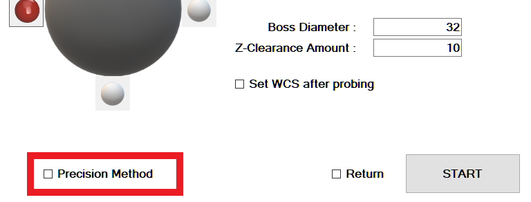
After a Precision Calibration has been completed, all Probing Cycles within the ProbeApp that support Precision Probing will show a Precision Method check box
When to use the Precision Calibration
As described in more detail in the Standard TP Calibration Chapter, the geometry of a mechanical Touch Probe is causing the pre-travel distance of the probe stylus (this is the distance from the moment the probe tip touches the surface to the moment the probe is generating the trip signal) to be non-uniform around a 360 degree circle. That meanst the pre-travel distance can vary significantly based on the angle the probe stylus is tripped.
If you are unsure how well your touch probe performs regarding pre-travel variations, I recommend to create a Trip Map as descibed in Chapter Touch Probe Trip Map.
The Trip Map will help to find the best position in the Touch Probe Trigger Pattern that has the least pre-travel variance in the X+/X- and Y+/Y- direction. It will also give you a pretty good picture of what overall accuracy you can expect from your touch probe.
If the pre-travel distance in the four main directions X+/X- and Y+/Y- varies significantly, you should definitely try the Precision Calibration Method as it will give you more accurate probing results overall.
Precision Calibration Process
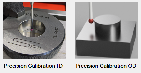
There is a Precision Calibration Process for Inner Dimensions (ID) and one for Outer Dimensions (OD):
Precision Calibration Inner Dimensions
The best way to Precision Calibrate a Touch Probe for Inner Dimensions is with a Ring Gauge that has a very precise known diameter.
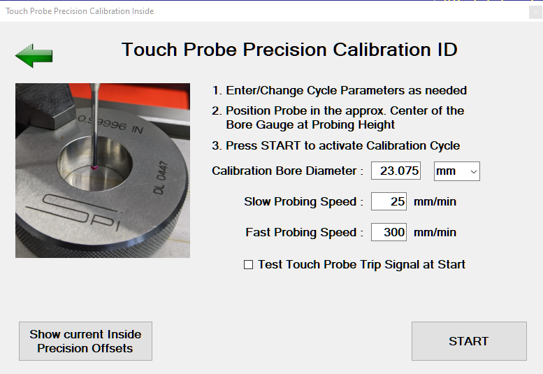
This calibration cycle has the following Input fields:
Calibration Bore Diameter
This is the diameter that’s usually engraved on the Ring Gauge. The units of the Ring Gauge can be selected. This will allow to use a mm Gauge on an Imperial machine (or vice versa) without having to convert the diameter manually to match the machines units.
Probing Speed
The default fast an slow probing feed rates are pre-populated. Only change these feed rates if you want to experiment if you can get more precise results by reducing the feed rate of if you can increase the feed rate without impacting the accuracy.
Note that changing the feed rates here does not change your default probing feed rates configured in CNC12. If you experimented here with feed rates and want to change them permanently, you have to make those changes manually in the CNC12 parameter section (Parameter 15 = Slow Probing Feed Rate, 14 = Fast Probing Feed Rate)
Test Touch Probe Trip Signal at Start
If this box is checked, the calibration cycle will start with a loop looking for a touch probe trip signal. Trip the touch probe manually and the loop will end with a confirmation message that the trip signal was recognized.
Show current Inside Precision Offsets Button
This button will only show if an ID Precision Calibration process has been done before. This button will open a screen that will show the currently configured offset values:
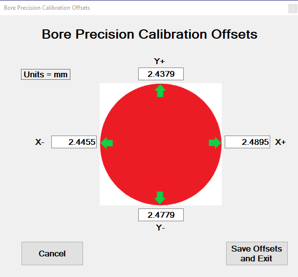
This screen does allow to fine-tune offset parameters if needed and save the new offsets.
START
Here’s now where the Precision Calibration process differs significantly from the Standard Calibration process.
After all data has been entered and the START button has been pressed, a ProbeApp message will pop-up describing the process:
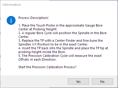
- In a first step, a regular Bore Cycle with the Touch Probe will be run to find the center of the Bore
- The Touch Probe should then be replaced with a Center Finder to fine-tune the spindles center position within the gauge bore. This will set the real spindle center position in relation to the bore.
- After the real center has been set, the TP is inserted again into the spindle and placed at probing height.
- The Precision Calibration cycle will now measure the exact distance in all four directions (X+/X- and Y+/Y-) from the center position to the point when the TP generates the trip signal and calculates the precision offset values in each direction.
After pressing the Yes buttton, each of the steps will be initiated with a message and needs to be confirmed with a Cycle Start:

After the Bore Cycle has finished the spindle will be at the bore center position as accurately as the TP’s precision this allows.
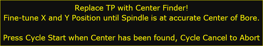
In this step a Center Finder is used to verify how far the current spindle center position is offset from the real bore center and the X and Y axis positions need to be adjusted until the Center Finder indicates that the spindle center is positioned at the real center of the bore.
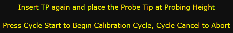
Now insert the TP again and place the probe tip at probing height within the gauge bore. Make sure the X and Y axis positions are not moved.
The Precision Offsets are now been measured in the X+/X- and Y+/Y- directions and presented on the Offset Screen
The Cancel button will discard these offsets, the Save and Exit button will save these offsets which will activate the Precision Method check box in all the ProbeApp probing cycles that support precision probing.
Precision Calibration Outer Dimensions
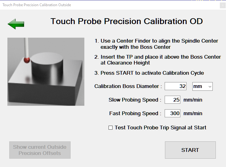
Use an object that has a very precise known outer diameter like a ball bearing.
This calibration cycle has the following Input fields:
Calibration Boss Diameter
The units of the Boss Diameter can be selected. This will allow to use an object with a known diameter in mm on an Imperial machine (or vice versa) without having to convert the diameter manually to match the machines units.
Probing Speed
The default fast an slow probing feed rates are pre-populated. Only change these feed rates if you want to experiment if you can get more precise results by reducing the feed rate of if you can increase the feed rate without impacting the accuracy.
Note that changing the feed rates here does not change your default probing feed rates configured in CNC12. If you experimented here with feed rates and want to change them permanently, you have to make those changes manually in the CNC12 parameter section (Parameter 15 = Slow Probing Feed Rate, 14 = Fast Probing Feed Rate)
Test Touch Probe Trip Signal at Start
If this box is checked, the calibration cycle will start with a loop looking for a touch probe trip signal. Trip the touch probe manually and the loop will end with a confirmation message that the trip signal was recognized.
Show current Inside Precision Offsets Button
This button will only show if an ID Precision Calibration process has been done before. This button will open a screen that will show the currently configured offset values:
This screen does allow to fine-tune offset parameters if needed and save the new offsets.
START
After all data has been entered and the START button has been pressed, a ProbeApp message will pop-up describing the process:
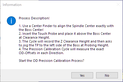
- Before the OD Calibration Cycle starts,, the Spindle Center must be exactly aligned with the Bore Center with a Center Finder.
- After the Spindle Center is aligned with the Boss Center, insert the TP and place it above the Boss Center at Clearance Height.
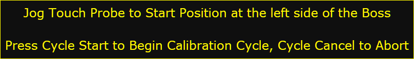
- Starting the Cycle now will record the Z Clearance Height of the TP above the Boss and a Message will ask to jog the TP down to the left side of the Boss at Probing Height.
- The Precision Calibration cycle will now measure the exact distance in all four directions (X+/X- and Y+/Y-) from the Boss center position to the point when the TP generates the trip signal and calculates the OD precision offset values in each direction.
After pressing the Yes buttton, each of the steps will be initiated with a message and needs to be confirmed with a Cycle Start:

The Z Clarance Height of the Touch Probe abovethe Boss is being recorded and the next Message will pop-up:
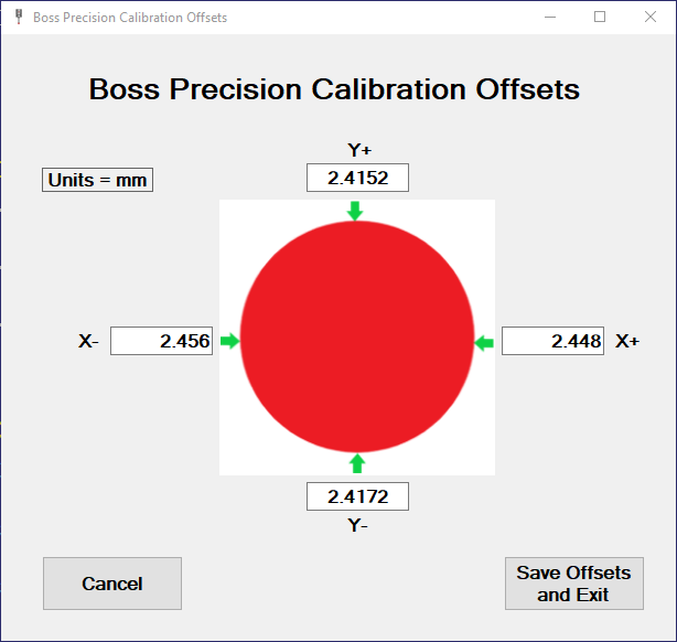
The Precision Offsets are now been measured in the X+/X- and Y+/Y- directions and presented on the OD-Offset Screen

The Cancel button will discard these offsets, the Save and Exit button will save these offsets which will activate the Precision Method check box in all the ProbeApp probing cycles that support precision probing.