ProbeApp for Centroid CNC12
ProbeApp for Mill & Routers that integrates with Centroid CNC12
Project maintained by swissi2000 Hosted on GitHub Pages — Theme by mattgraham
Standard Tripple Corner Plate
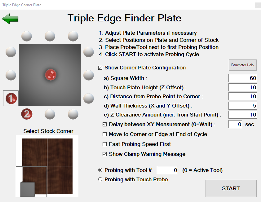
Description
Find the exact corner position of a stock and measure Tool Height Offsets. This probing cycle is available for all versions of CNC12. This probing cycle is extremly versatile as the plate can be placed on any corner of the stock and any corner of the plate can be used for measurements.
Probing cycles can be made with a tool or with a Touch Probe.
Implementation Details
This probing cycle supports the plate being placed on any corner of the stock. Make sure the Select Stock Corner selection matches the actual plate position. Any corner, a single side or the top of the plate can be used for measurements.
Having the option to use the back inside corner of the plate to find the stock corner gives the safty probing option. In the case the probe is malfunctioning for some reasons, the probing move would just push the plate away from the stock without breaking the tool or cause other damage.
For any probing cycle involving a plate corner or single side, place the tool/probe at the selected Corner Position 1 or the marked single side position. The Z-Height has to be set at the level the measurements needs to be taken on the surface.
If tool flute alignment is necessary for accurate contact, make sure that the check box Delay between XY Measurement is checked to allow time to reposition the flutes for the second measurement.
If a Z-Axis measurement is combined with a corner measurement, the Z measurement position will be taken at the exect center of the plate.
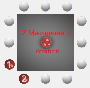
If a Z-Axis measurement is combined with a single side measurement, the Tool/Probe will move to the center of the plate at the position the side wall measurement is taken for the Z-Axis measurement.
For a single Z-Axis Tool Height Offset measurements, the Tool/Probe can be placed anywhere above the plate Z-Surface for the Z-Axis measurement.
At the end of the probing cycle, the Set WCS message will be displayed:
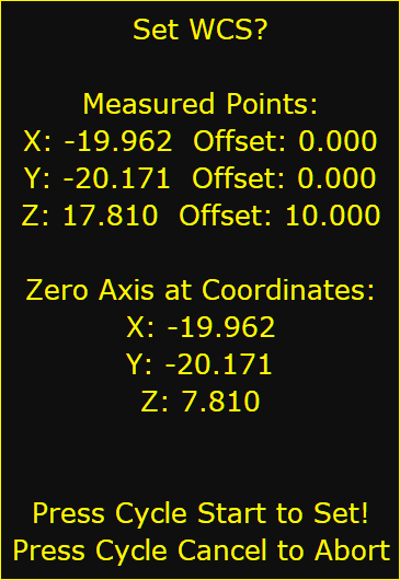
Note that this message can be surpressed if a direct WCS reset is desired withou a prior Set WCS message display. See Configuration Options for details.
See all the configuration parameters below on details how to customize the probing cycle.
Configuration Parameters
Before this probing cycle can be used, the plate parameters need to be entered. After the plate has been setup, the check box Show Corner Plate Configuration can be unchecked to unclutter the screen.
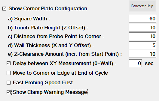
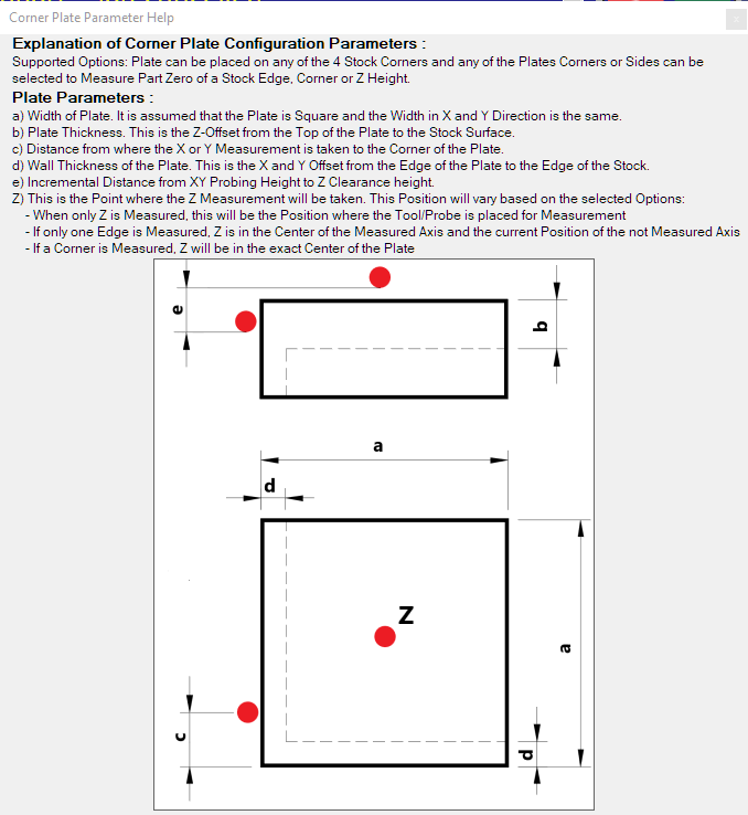
Press the button Parameter Help for a graphic explaining the parameters a) b) c) and x) y) z).
Additional options that are available are explained below.
Delay between XY Measurement
If measurements are taken with a cutter, it might be necessary to adjust the position of the tool flute to get an accurate measurement in each direction. This option allows to add a pause or delay between the X and Y measurements in the bore to give time to make this adjustment.
The default value for this option is 0 which indicates that the probing cycle will stop with a message which needs to be confirmed with a Cycle Start before the probing cycles continues. A value larger than 0 specifies the number of seconds the Tool Adjustment Message is being displayed before the probing cycle continues.
Move to Corner at the End of Cycle
This option makes no difference when a single Z-Axis measurement is taken as the probing cycle will always end at the Z-Clearance Height where the Z measurement is taken.
If this option is unchecked, the probing cycle will end at the Z-Clearance Height where the last measurment was taken.
If this option is checked, the center of the Tool/Probe will move to the Z-Clearance Height above the calculated corner point of the stock at the end of the cycle. If only a single side was selected, the center of the Tool/Probe will move to the Z-Clearance Height above the measured stock edge position.
Fast Probing Speed First
If this option is selected, all probing moves will occure at fast probing feedrate first followed by a final probing move at slow probing feedrate.
If this option is unchecked, only one probing move in slow probing feedrate will be done. While using a tool for the probing cycle, it is recommended to use slow probing feedrate only.
Show Clamp Warning Message
If this option is selected, a warning message will be diplayed before the probing cycle starts. The message needs to be confirmed with a Cycle Start before the probing cycle continues.

The Clamp Warning Message can be customized. See Configuration Options for details.
Probing with Tool or Touch Probe
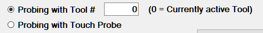
Probing cycles can be made with a tool or a Touch Probe. Because the contact point of the tool/probe that triggers the touch off signal at the plate for a X/Y measurement is the outside of the tool/probe, the probing cycle needs to know the exact diameter of the tool/probe to calculate the center point.
If Probing with Touch Probe is selected, the Touch Probe needs to be setup and configured properly in the CNC12 Wizard as the probing cycle will depend on the CNC12 probing parameters.
If Probing with Tool # is selected, it is IMPORTANT that the tool diameter of the selected tool is properly configured in the CNC12 Offset Library for X/Y measurements. So if Tool # 6 has been choosen that has a diameter of 4mm, the CNC12 Offset Library MUST be configured like this:
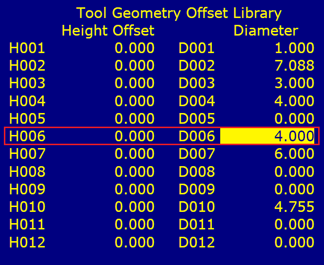
For Z-Axis measurements, the Tool Diameter plays no role but the Tool Height Offset is important. If every tool is being touched off before it’s been used, make sure the Height Offsets in the CNC12 Offset Library are all set to 0 like the example above.
By default the Tool # is set to 0 which means that the currently active tool in CNC12 is being used. Make sure that CNC12 does have the correct tool # active when you make this selection and that the CNC12 Offset Libray has the correct Offsets for that tool:
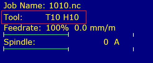
In the case where the CNC12 Tool Offset Library does have different Tool Height Offsets, it is important that the Tool # does match the tool # used in the job file.
Start the Probing Cycle
After making all the selections necessary on the screen, pressing the START button will start the parameter validation. A message will be displayed if any of the parameters are missing or invalid
If no validation issues have been found, the ProbeApp will write all the necessary probing commands to
c:\cncm\ncfiles\probing_cycle.cnc
The ProbeApp will close giving control back to CNC12

At this point the Probing Cycle can be started by pressing Cycle Start or aborted with Cycle Cancle.
Closing ProbeApp without a Probing Cycle selections
The Probing Cycle screen can be closed by either pressing the X on the top right corner of the window or pressing the Green Back Arrow on the top left. This will open the ProbeApp main window where the Exit button can be pressed.
Control will go back to CNC12 where this message will be displayed:
Pressing Cycle Cancle will terminate the cycle immediately. Pressing Cycle Start will bring up this message:
Pressing Cycle Start at this point will also terminate the cycle.