ProbeApp for Centroid CNC12
ProbeApp for Mill & Routers that integrates with Centroid CNC12
Project maintained by swissi2000 Hosted on GitHub Pages — Theme by mattgraham
Method 2: Using a single, Movable Tool Touch Off
Description
This method uses only one Movable Tool Touch Off Plate (TT). The movable TT is being placed on top of the workpiece to find the exact position of the top surface.
- Test TT (Movable TT only): This will add a TT Trigger Check before the probing of the Movable TT is executed to assure that the TT is functioning properly.
- Fast Probing Speed First: This check box will always default to the selected configuration setting and allows to temporarely enable or disable the fast probing move.
- Use WCS#: This allows to select the WCS# that’s being reset by this probing cycle. Default is always the currently active WCS#. The machine will remain in the currently active WCS and only switches quickly to the selected WCS for the Reset.
Two cycle options are available for this method.
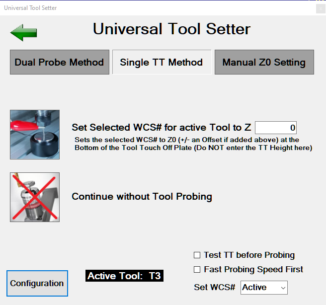
Cycle 1: Set Selected WCS# for active Tool to Z0
Uses the Movable TT on top of the workpiece to probe the active tool and set Z0 (plus an optional offest) for the selected WCS#.
Three options can be selected on the bottom right to customize the probing cycle:
- Test TT before Probing: This will add a TT Trigger Check before the probing of the Movable TT is executed to assure that the TT is functioning properly.
- Fast Probing Speed First: This check box will always default to the selected configuration setting and allows to temporarely enable or disable the fast probing move.
- Use WCS#: This allows to select the WCS# that’s being reset by this probing move. Default is always the currently active WCS#. If another WCS# than the currently active is selected,
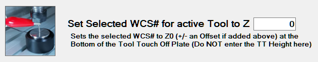
Cycle 2: Continue without Tool Probing
If the Tool Setter screen is being launched by a M6 Tool Change command but no Tool Touch Off is needed, the Cycle 2 button allows to continue the job without a Tool Touch Off.
Configuration for Single TT Setup
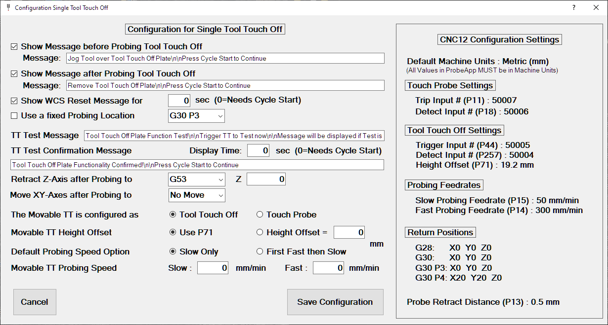
The Configuration screen allows for a very flexible customization of the probing cycle. The right side of the Configuration screen shows the currently configured CNC12 parameters related to Probing and Return Positions. This allows to verify the correctness of the CNC12 settings while customizing the ProbeApp Tool Setter configuration.
These options can be changed at any time and the ProbeApp will dynamically generate the necessary probing commands for CNC12 based on current configuration settings.
Check out the details below for each of these options.

If this option is checked, CNC12 will display a Message before the probing move is executed. The message can be customized in the Message box (adding \n does create a line break in the message box).
Be aware that not checking this box does directly engage the probing cycle when the Cycle Start button is pressed. A Remainder to attach a Clip could be added here. The message needs to be confirmed with a Cycle Start.

This will display a message after the probing cycle with the TT has finished and the tool has been retracted. A Remainder can be added here to remove the TT and Clip.
Be aware that not checking this box will directly move the Tool to the X and Y return position if one is configured.

This will display a WCS Reset message after the TT has been probed. This allows to verify if Z0 has been set correctly for the selected WCS#. A time in Seconds can be set for the lenght of the message display before the cycle continues. A time value of 0 will require to confirm the message with a Cycle Start.

This option can be used if a tool touch off always takes place at the same location.
The available options are:
- G28 (same as G30 P1)
- G30 (same as G30 P2)
- G30 P3
- G30 P4
- G53 with selectable X and Y Position

This is the text of the message that’s being displayed before the test cycle of the TT is being engaged if the Test TT option was selected om the main screen. Customize this message do your requirements. A \n within the message will force a line break in the CNC12 message box.

This is the message that will be diplayed when the TT trigger signal was succesfully recognized. The lenght of the display time in seconds can be selected for this message. A time value of 0 will require the message being confirmed with a Cycle Start.

This setting defines the Z position the machine should retract to after probing the TT.
The available options are:
- G28 (same as G30 P1)
- G30 (same as G30 P2)
- G30 P3
- G30 P4
- G53 with selectable Z Position
- Start Position
The configuration screen does display all the Return Values as they are currently configured in CNC12 (Setup[F1] -> Part[F1] -> WCS Table[F9] -> Return[F1])
The G53 option does allow to select any Z machine coordinate position but be aware that MCS Z0 is usually on the top going down in negative direction so you would need to enter a negative position value.
The option Start Position will mark the current position at which the measurement of the TT was kicked off.
If a Z return value has been selected that is below the probing point, an error message will be displayed and the probing cycle will be aborted.

Specifies the X and Y position the tool should move to at the end of the probing cycle.
The available options are:
- G28 (same as G30 P1)
- G30 (same as G30 P2)
- G30 P3
- G30 P4
- G53 with selectable X and Y Position
- No Move
The default selection is No Move.

This probing cycle supports a Tool Touch Off device being installed as a Touch Probe.

If you have configured the height of the Tool Touch Off in the CNC12 Wizard it will be stored in CNC12 System Parameter P71.
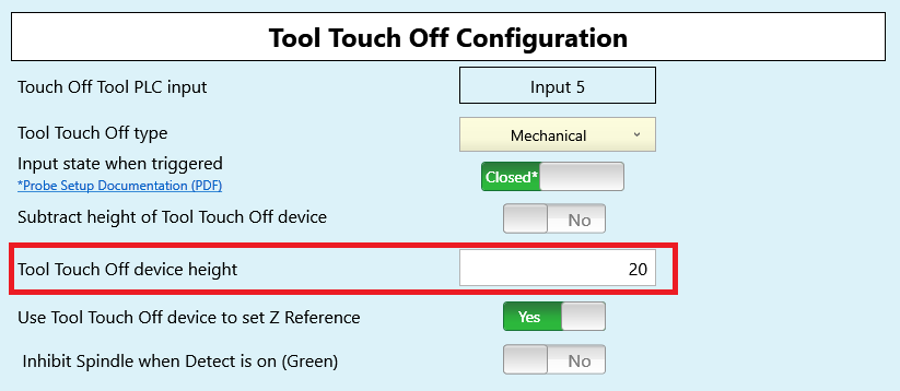
There is some unexpected behavior in the way the Wizard configures P71 as the value you enter in the Wizard is positive but when you look up the parameter in CNC12 it will be stored as a negative number. If you change P71 in CNC12 to a positive number it will show up in the Wizard as a negative number. To work around this issue, the ProbeApp will always use the absolute value of P71 and will do the correct thing with it.
You can always use P71 even when your Movable TT is configured as Touch Probe. If the TT Height is not set in CNC12 use the alternative option and enter the Height Offset here.
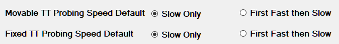
The probing moves can be executen in a fast probing move first followed by a slow probing move or a slow probing move only.
With this selection you define what your preferred, default probing behavior is. This setting impacts the default setting of the check box Fast Probing First on the Cycle Main screen.
If you select First Fast then Slow here, the check box on the Cycle Main screen will always be selected by default and vice versa.

This allows to configure a dedicated slow and fast probing feedrate for the movable TT. These speed settings are only for the Tool Setter cycle and do not impact the probing speed settings in CNC12.
If these probing feedrate values are left at 0, the default CNC12 probing feedrate values configured in the Probe Section of the CNC12 Wizard are being used.
Note that the units (mm/min or inch/min) are displayed depending on the default units of the machine.