ProbeApp for Centroid CNC12
ProbeApp for Mill & Routers that integrates with Centroid CNC12
Project maintained by swissi2000 Hosted on GitHub Pages — Theme by mattgraham
Tool Offset Manager: Reference Tool Method
Description
This Method is for machines that do have fixed Tool Holders but do not have a constant distance between the Z-Home position and the machine table. A good example for such a machine type is a Knee-Mill where the machine table can be moved up and down.
For this type of machine, the Reference Method must be used. With this method, the Reference Tool must be used to establish a Reference Point on a Reference Surface anywhere along the Z-Axis. This point is usually set where the Reference Tool touches the Tool Touch Off device. The Height Offset of the Reference Tool must always be 0 by definition and the Height Offsets of all the other tools are measured and calculated as the difference in tool lenght compared to the lenght of the Reference Tool.
The Reference Tool can be the Touch Probe if one is available, any tool in the Tool Library or a dedicated Reference Tool that’s not part of the Tool Library.
The Reference Tool doesn’t even have to be an actual tool. It can be just a piece of rod mounted in a dedicated tool holder. It is important that the lenght of the Reference Tool stays always the same as this tool will always be used to establish a new reference point from where additional tools that need to be added to the tool library will be measured. If the lenght of the Reference Tool changes, all Tool Height Offsets need to be re-measured.
It is very convenient to use the Touch Probe as the Reference Tool but keep in mind that when you break the styli of the Touch Probe and it needs to be replaced, the new styli might not have exactly the same lenght and all Tool Height Offsets need to be re-measured. Therefore it might be a better option to use a dedicated tool holder with a tool that’s never been used or with a piece of rod that will always keep the same lenght and is never in danger of being broken.
Configuration Settings
The configuration page for the Reference Tool Method does offer the following settings:
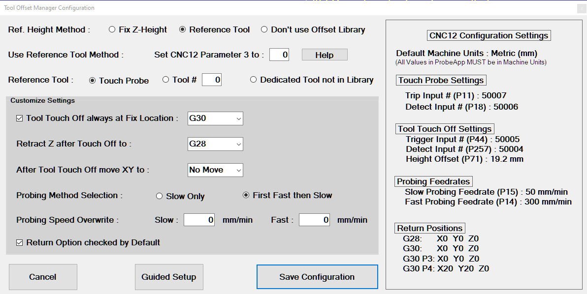
CNC12 Configuration Settings
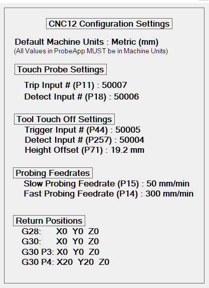
The right side of the Configuration page shows all the current CNC12 configuration settings related to Probing just for reference. The coordinates of the Return Positions G28, G30, G30 P3 and G30 P4 must be configured in CNC12 directly and can’t be configured in the ProbeApp (Setup[F1] -> Part[F1] -> WCS Table[F9] -> Return[F1])
CNC12 Parameter 3

For the Reference Tool Method, Parameter 3 will be set to 0 by default. There’s no need to change this unless you want to enable one of the other options provided by Parameter 3:

Note that the ProbeApp can’t change this parameter while CNC12 is running. You will get a message that you need to restart CNC12 for this Parameter to change. It’s also important to know that the setting of Parameter 3 does not have any impact as long as you only use the ProbeApp-Tool Offset Manager to measure the Tool Height Offsets. Only if you want to use the CNC12 built in functions to add Tool Height Offsets to the Tool Offset Library it is important that this Parameter is set correctly.
Tool Touch Off Location

Check this box if you want the machine to move to a fixed point to touch off a tool.
Possible Options that can be configured as the fixed touch off location are:
- G28
- G30
- G30 P3
- G30 P4
- G53 X_ Y_
Note that the currently in CNC12 configured return positions for G28, G30, G30 P3 and G30 P4 are displayed on the right side of the configuration screen. The default option is G30. Changes to these return positions must be done directly in CNC12 (Setup[F1] -> Part[F1] -> WCS Table[F9] -> Return[F1]).
It is also possible to configure the X and Y machine coordinates (MCS) with the G53 option directly in the ProbeApp.
Z Retract Position after Tool Touch Off

Configures the preferred retract position of the Z-Axis after the Tool Touch Off is completed.
Possible options are:
- G28
- G30
- G30 P3
- G30 P4
- G53 Z_
- Start Pos
See comments above about these options. An additional option here is to retract the Z-Axis to the Start Position, which is the position at which the Tool Touch Off Cycle was started. This can save time if you don’t want to retract Z all the way up after a Tool Touch Off but be careful when you combine this option with the option to move the X and Y axes to a certain position after the Tool Touch Off as you need to make sure you always have enough Z Clearance.
The default option is G28.
X and Y Return Positions after Tool Touch Off

Configures the preferred return positions of the X and Y-Axis after the Tool Touch Off is completed.
Possible options are:
- G28
- G30
- G30 P3
- G30 P4
- G53 X_ Y_
- No Move
- G0 X_ Y_
In addition to the G28, G30 and G53 return positions is the option to return to the current WCS Zero point with the G0 command.
The default option is No Move.
Probing Method Selection

This selection depends on the type of Tool Touch Off device being used. If the Tool Touch Off device has a spring loaded touch off plate, it is recommended to do a more aggressive fast probing move first followed by a slow accurate probing move.
If the Tool Touch Off device is a fixed metal plate it is recommended to skip the first fast probing move and run a slow probing move only to protect the tool.
Probing Speed Overwrite

These settings allow overwriting the default CNC12 slow and fast probing speeds just for the Tool Touch Off cycles. If these values are left at 0, the default CNC12 probing speeds are being used. The currently configured CNC12 probing speeds are listed on the right side of the configuration screen.
Return Option

The Tool Offset Manager main screen has a Return check box that will tell the ProbeApp to re-open after data has been saved or tools have been measured. This check box here in the configuration screen configures if the Return check box on the Tool Offset Manager main screen should be checked by default or not.
Button Functions

- Cancel: Will abort the setup process
- Guided Setup: Use to re-run the Guided Setup if machine information has changed
- Save Configuration: Saves the configuration settings and opens the Tool Offset Manager
Instructions Page
After the configuration settings are saved, an Instruction screen like this will be displayed:
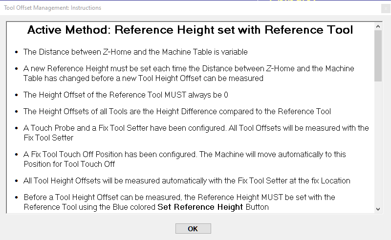
Read this information carefully as the instructions are dynamically created based on the configuration settings. Pressing the OK button will close the Instructions page but the page can be re-opened anytime again with the Instructions button on the Tool Offset Manager main screen.
Tool Offset Library Manager
A typical Tool Offset Library Manager main screen for the Reference Tool Method looks like this:
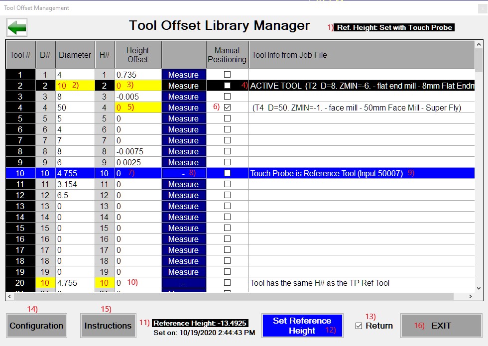
Feature List
1) Reference Height Method
Indicates which Reference Height Method is currently active
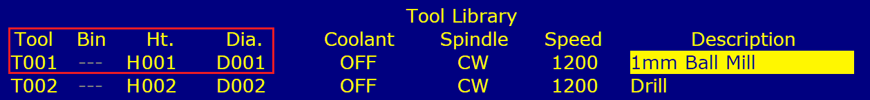
2) Not matching Tool Diameter
All values that are highlighted with red numbers on yellow background need attention. In this case, the Tool Diameter currently stored in the CNC12 Tool Library does not match the Tool Diameter of this tool listed in the currently open job file and is being highlighted as a warning (see 4) about how Tool Information of the currently open Job File is imported into the Tool Offset Manager).
3) Missing Tool Height Offset
Tool T2 is needed in the currently open job file but does not have a Tool Height Offset recorded in the CNC12 Tool Offset Library and is being highlighted as a warning that this tool needs to be measured and added to the tool offset library before it can be used correctly in the job file execution.
4) Tool Information from the currently open Job File
When the Tool Offset Manager starts up, the ProbeApp is reading the currently open job file and imports the tool information if the Post Processor that created the job file has placed that information at the beginning comment section of the job file. The Tool number must be in the form of T1, T01 or T001 and the Diameter in the form of D=2.25. Here’s an example how Fusion 360 inserts such Tool Information at the start of a job file as comment:
(T2  D=8. ZMIN=-6. - flat end mill - 8mm Flat Endmill)
(T4  D=50. ZMIN=-1. - face mill - 50mm Face Mill - Super Fly)
Also the currently active tool is labeled as such and is also being highlighted with a black background.
5) is same as 3)
6) Manual Tool Positioning
If tools are measured with a Tool Touch Off device at a fixed location, some tools that have a large diameter or are oddly shaped can’t be measured automatically and need to be positioned manually above the Tool Touch Off device before they can be measured.
If this checkbox is being checked for a tool, the tool touch off probing cycle will pause above the Tool Touch Off device with the message to manually position the tool. After the tool has been positioned properly, pressing the Cycle Start button will resume the touch off process.
This checkbox also works for machines that don’t use the Tool Offset library for Tool Height Offsets and are using the ProbeApp-Tool Setter instead to touch off each tool with a fixed Tool Touch Off device.
7) Height Offset of Reference Tool
The Height Offset of the Reference Tool always needs to be 0 by definition as all other tool height offsets are measured and calculated as lenght differences compared to this tool. This value is forced to be 0 annd can’t be changed.
8) Measure Button
The Measure Button for the Reference Tool is always disabled as this tool needs to have a Height Offset of 0. The Set Reference Height Button needs to be used to establish the Reference Height with the Reference Tool (see 12).
For all the other tools, press the Measure Button to measure the Tool Height Offset of that tool and add it to the CNC12 Tool Offset Library. After the Measure button has been pressed, the ProbeApp will close and give control to CNC12. Press the Cycle Start button to execute the Tool Touch Off cycle.
If the Return checkbox was checked (see 11) for more information about the Return function), the Tool Offset Library Manager will open again and show the measured Tool Height Offset and allows for more tools to be measured. If the Return checkbox was not checked, the Tool Offset Library Manager will not reopen and the job file will continue if the ProbeApp was started from a running job or otherwise just return to CNC12.
9) Reference Tool Marking
The Reference Tool is labeled as such and is also highlighted with a blue background. In this case, the Touch Probe is the Reference Tool.
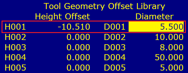
10) Diameter and Height Offset Numbers
It is important to understand that the Diameter Offset number (D#) and the Height Offset number (H#) are not the same as the actual Diameter value (D=5.5) or Height Offset Value (H=-10.51). The CNC12 Tool Library stores the Tool # and for each tool it holds the D# and H# that are associated with that tool. By default, the T#, D# and H# all match, which means that T1 has D1 and H1 assigned. The actual Diameter and Height Offset values for D1 and H1 are stored in a separate table, the Tool Geometry Offset Library.
The CNC12 Tool Library allows to assign any D# or H# to any tool. This can severely complicate things if you start to mess with these assignments as you cannot just assume that T1 has D1 and H1 assigned as it could be any number in the valid range of 1 - 200.
If any D# or H# in the CNC12 Tool Library does not match the T#, the Tool Offset Library Manager will highlight that D# or H# with red font on yellow background to bring that to your attention. If a tool has the same H# as the Reference Tool, this tool will also be forced to have a Tool Height Offset of 0 as one Height Offset Number (H#) can only hold one Height Offset value. Also if several tools are sharing the same D# or H#, if one of those tools is changed to a different D= or H= value, all tools in the table sharing the same D# or H# will be updated.
Note that the ProbeApp-Tool Offset Library Manager doesn’t allow you to change D# and H# to T# assignments. Such re-assignments must be completed in the CNC12 Tool Library directly.
11) Reference Height
This shows the currently set Reference Height and the date and time when the Reference Height was set. This will give an indication if a new Reference Height need to be established first before a new Tool Height Offset can be measured. You will get a warning message if you try to measure the Tool Height Offset of a new tool and the Reference Height was last established more than 24 hours ago.
It is good practice to always establish a new Reference Height before measuring a new Tool Height Offset to eliminate any possibility that the machine table might have moves since the last Reference Height was established.
12) Set Reference Height Button
Use this button to establish the new Reference Height with the Reference Tool before measuring the Tool Height Offset of new tools to add them to the Tool Offset Library.
Place the Tool Touch Off device on any surface, place the Reference Tool into the spindle and touch it off to set the Reference Height. After the Reference Height is set with the Reference Tool, insert the new tool to be measured into the spindle and touch it off at the same location.
13) Return Function
If the Return checkbox is checked, the Tool Offset Library Manager will reopen after the ProbeApp has closed to save data in CNC12 or to execute a Tool Touch Off cycle. Use the Configuration settings to configure if the Return checkbox is always checked by default or not.
14) Configuration Button
When the Tool Offsetter is being launched for the first time, the Guided Setup will automatically start to generate the initial setup and configure everything according to the answers given. The Configuration Button allows reopening the configuration screen to customize settings.
If additional Probing Devices have been added to a machine or the tool holding method has changed, it is recommended to run the Guided Setup again which is accessible from the Configuration screen.
15) Instructions
Press the Instructions Button anytime to reopen the Instructions screen that holds information specific to the current configuration.
16) EXIT/SAVE Button
The status of this button will change between EXIT and SAVE depending if there’s information that needs to be saved in CNC12. If this button is highlighted in bright green and displays SAVE, there is information that has changed and updates in CNC12 need to be done. Pressing the SAVE Button will close the ProbeApp and the Cycle Start button needs to be pressed to update information in CNC12.
If this button shows SAVE and a Tool Height Offset measurement is started with the Measure Button, the Measure cycle will take care of saving the pending updates in CNC12 automatically.